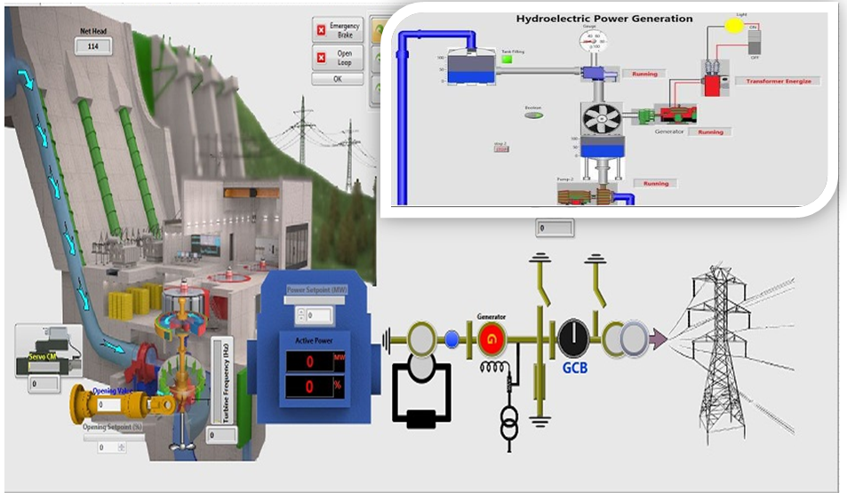
A Digital Governing System (DGS) is an electronic and computer-based control system used to regulate the speed, power output, and operating stability of a hydropower turbine-generator unit. The system receives signals from sensors and controls the guide vane opening or runner blade position through hydraulic actuators to maintain the required speed and power.
1. Main Components of Digital Governing System:
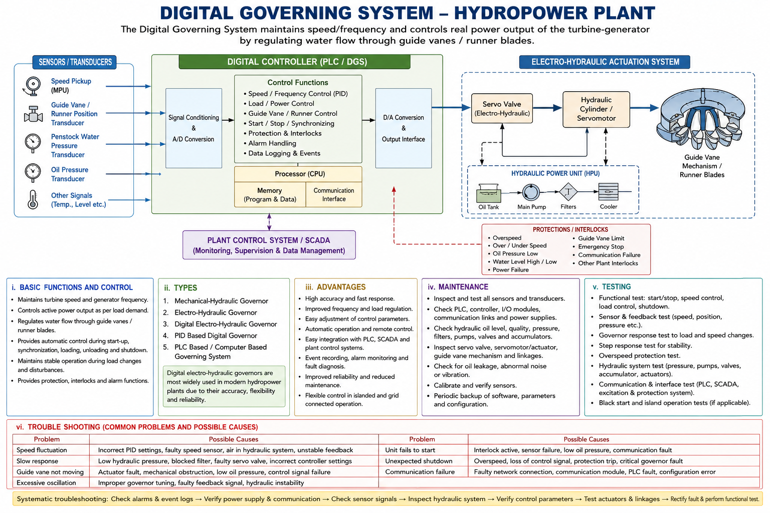
The major components of Digital Governing System are: 1. Speed Sensor / Speed Pickup → 2. Position / Feedback Sensors → 3. Pressure and Process Transducer → 4. Digital Governor Controller → 5. Human Machine Interface (HMI) → 6. Input / Output Module → 7. Electro-Hydraulic Servo System → 8. Hydraulic Power Unit (HPU) → 9. Actuating Mechanism → 10. Communication Interface → 11. Protection and Interlocking System → 12. Power Supply and Backup System
2. Basic Function and Control:
The main function of a digital governing system are:
i. Maintain turbine speed and generator frequency at the rated value.
ii. Control the Active Power output according to the load.
iii. Regulate the water flow through guide vanes and runner blades.
iv. Provide automatic control during start-up, synchronization, loading, un-loading and shutdown.
v. Maintain the stable operation during load changes and disturbances.
vi. Provide protection and interlocking functions during abnormal conditions.
3. Types of Governing Systems
Common types of Governing System are:
i. Mechanical-Hydraulic Governors - Use mechanical speed sensing and hydraulic control.
ii. Electro-Hydraulic Governors - use electronic control signals with hydraulic actuator.
iii. Digital Electro-Hydraulic Governor - use PLC / Microprocessor based digital control with hydraulic actuation.
iv. PID based Digital Governor - use Proportional, Integral and Differential control algorithms for accurate regulation.
v. PLC or Computer Based Governing System - Governor Control system integrated with plant control and SCADA System.
4. Advantages:
The main advantages include:
i. High accuracy and fast response.
ii. Improved frequency and load regulation.
iii. Easy adjustment of control parameters.
iv. Automatic operation and remote control.
v. Easy integration with PLC, SCADA, and plant control system.
vi. Event recording, alarm monitoring and fault diagnosis.
vii. Improved the operational reliability and reduce the maintenance requirements.
viii. Flexible control during islanded and grid connected operations.
5. Maintenance:
Regular maintenance includes:
i. Inspection and testing of speed, position, pressure, and feedback sensors.
ii. Checking the PLC, controller, input/output modules, communication links, and power supplies.
iii. Inspection of hydraulic oil level, quality, pressure, filters, pumps, valves, and accumulators.
iv. Checking of the servo motors, servomotor's actuators, guide vane mechanisms, and linkages.
v. Checking for hydraulic oil leakage and abnormal vibration or noise.
vi. Verification and calibration of sensors and transducers.
vii. Periodic backup of control software, parameters, and configuration files.
Maintenance may be routine/preventive, predictive, and corrective.
6. Testing:
Important of Governor System includes:
i. Functional test:- Verification of start, stop, speed control, load control, and shutdown functions.
ii. Sensor and feedback test:- Checking speed, position, pressure, and flow signals.
iii. Governor response test:- Verification of response to changes in speed and load reference.
iv. Step-response test:- Checking the dynamic response and stability of the governor.
v. Overspeed protection test:- Verification of the emergency shutdown system.
vi. Hydraulic system test:- Checking oil pressure, pump operation, accumulator, valves, and actuators.
vii. Communication and interface test:- Verification of signals between the governor, PLC, SCADA, excitation system, and protection system.
viii. Black-start and island operation tests, where applicable.
7. Troubleshooting:
Common problems of Governor System and their possible causes includes:-
Problem | Possible Causes |
|---|---|
| Speed fluctuation | Incorrect PID settings, faulty speed sensor, air in hydraulic system, or unstable feedback |
| Slow response | Low hydraulic pressure, blocked filter, faulty servo valve, or incorrect controller settings |
| Guide vane not moving | Actuator fault, mechanical obstruction, low oil pressure, or control signal failure |
| Excessive oscillation | Improper governor tuning, faulty feedback signal, or hydraulic instability |
| Unit fails to start | Interlock active, sensor failure, low oil pressure, or communication fault |
| Unexpected shutdown | Overspeed, loss of control signal, protection trip, or critical governor fault |
| Communication failure | Faulty network connection, communication module, PLC fault, or configuration error |
The Digital Governing System is a critical control system of a hydropower plant. Proper maintenance, periodic testing, accurate calibration, and systematic troubleshooting are essential for safe, stable, and reliable operation of the turbine-generator unit.
Comments